
As we described in our previous article, Earth Observation (EO) is a key technology in constant evolution that gathers, collects, and extracts valuable and actionable information from images from the surface of the Earth taken through satellites orbiting hundreds of km. In this technical note, we will detail how the Cactus team has designed and developed a solution to monitor power lines using EO data. In this collaborative Technical Note, our colleagues Alejandro Trujillo AI Engineer, Torsten Reidt AI Lead Engineer and Jose Laffitte Head of Engineering of Cactus provide insights on the hurdles and the solutions along the way. Our innovative approach leverages advanced Earth Observation technologies to effectively manage vegetation risks, improve safety, and ensure power infrastructure reliability.
How Cactus is using EO data to monitor infrastructure
At Cactus, we have designed a tool named TreeSight that, when fed with satellite images, enables monitoring of critical infrastructure such as electrical power lines.
The Challenge
Vegetation near power lines poses significant safety hazards, including the risk of power outages, fires, and safety/electrical hazards.
Managing these risks often requires tree trimming or removal, which can lead to conflicts over environmental and aesthetic concerns. Energy companies must balance maintaining reliable power supply with adhering to regulations and community expectations, especially as climate change increases the frequency of severe weather events. The most common mechanisms for monitoring electrical power lines today involve the use of helicopters and drones equipped with LiDAR technology. While these methods offer advanced capabilities in capturing detailed topographical data and identifying potential issues such as vegetation encroachment or structural damage, they also come with significant challenges. While LiDAR is effective, it is both costly and logistically challenging. Helicopter inspections are expensive due to the costs associated with aircraft operation, fuel, and crew. They also offer only limited coverage, requiring multiple flights to cover extensive networks, which can be hindered by weather conditions and challenging terrain, in fact, in the 2024 Summer campaign, Endesa spent 2.5 million euros only monitoring the electric cable infrastructure in Cadiz, rising to around 26 million for Andalucia as a whole.
Additionally, the need for skilled operators and the potential risks involved in flying over difficult terrains or populated areas further complicate implementation. These factors highlight the need for more cost-effective and scalable monitoring solutions in the power industry.
Ground inspections, which involve teams surveying power lines on foot or by vehicle, are labor-intensive and pose safety risks for the inspectors.
Satellites present a compelling alternative by offering a more cost-effective and scalable solution for monitoring power lines. Unlike helicopters, satellites can cover vast areas in a single pass, significantly reducing operational costs. Once in orbit, they provide continuous data collection without the need for ongoing, expensive aerial operations. Satellites equipped with high-resolution optical sensors can capture detailed imagery of power lines, allowing for the detection of issues such as vegetation encroachment or structural damage. Additionally, Synthetic Aperture Radar (SAR) on satellites can detect ground displacement and changes, helping to identify potential issues with power line supports or infrastructure.
Various solutions have been explored to address this issue, but they face challenges such as insufficient image resolution (requiring < 5 meters) or lack of precision in predictions. Some of these alternatives involve processing vast amounts of satellite images (e.g., Sentinel-2), and correlating its brightness patterns in the pixels with the measures taken through LiDAR. The algorithm then learns to associate certain textural and spectral patterns in the images with specific canopy heights. Once trained, the model relies solely on optical images to estimate canopy height.
Our solution, named TreeSight, takes a different approach and ensures the scalability and accuracy of the application while maintaining the high reliability of the information.

Our solution: TreeSight
Let’s dive deep into the solution our expert team has designed and developed to solve the challenge: We have selected Pleiades satellites to provide the images we are using in our analysis. One of the main criteria is its high resolution, reaching 0.5 meters per pixel, although some satellites been launched recently promise to improve this even further, such as Sentinel 2c.
TreeSight processes satellite data to calculate the NDVI index of a certain region, which is used to detect the presence of trees. It then determines three key parameters: tree position, shadow length, and direction vector. By incorporating the exact time the image was captured and considering factors such as the region under study, our software estimates critical indicators to assess whether a potential risk (the risk refers to the threat posed by vegetation, such as trees, growing too close to electrical power lines) exists in a given area. By cross-referencing this data with the locations of electrical power lines, operators can identify specific areas requiring maintenance to mitigate vegetation-related risks.
From an architectural perspective, our application is organized into multiple modules, as illustrated in the following figure. Each module is designed to handle specific functions, ensuring that the system is both scalable and efficient. This modular approach allows for better management, development, and maintenance, facilitating easier updates and integration of new features as needed. By segmenting the application into distinct components, we can optimize performance and ensure that each module operates independently, contributing to the overall reliability and flexibility of the system.
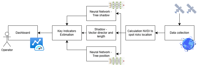
Let us now focus on each one of the main modules depicted above:
1. Normalized Difference Vegetation Index – NVDI
NDVI mapping is a powerful technique used in EO to assess and monitor vegetation health and cover. The NDVI is a remote sensing index derived from satellite imagery that measures vegetation health and density. It is calculated using the reflectance values of 2 specific spectral bands, the near-infrared band and the red band, the first one because of vegetation strongly reflecting near-infrared light, and the second one to quantify the absorption of red light during photosynthesis.
This method is highly efficient for identifying vegetation across vast areas, but its precision falls short when it comes to monitoring electrical systems. Additionally, different plant species emit varying levels of radiation during photosynthesis, making it difficult to establish a consistent threshold for detecting potential collisions with power lines. These limitations hinder its effectiveness in accurately assessing vegetation-related risks to critical infrastructure.
However, this method remains highly valuable for identifying areas free of vegetation, allowing us to focus on zones that don’t require inspection. In this case, we can establish a reliable threshold. By setting a fixed constant, we can confidently exclude regions where vegetation is not tall enough to pose a risk to the electrical system. The threshold is calibrated to be low enough to ensure no tall trees are present, yet high enough to eliminate as much unnecessary space as possible. This constant can vary based on the geographical zone being monitored and its specific climate or environmental conditions, optimizing the efficiency of the monitoring process.
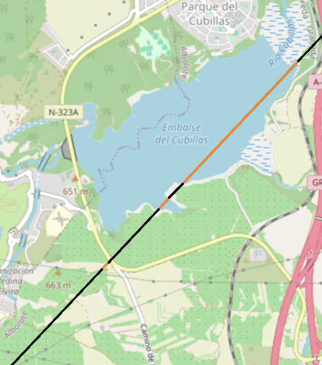
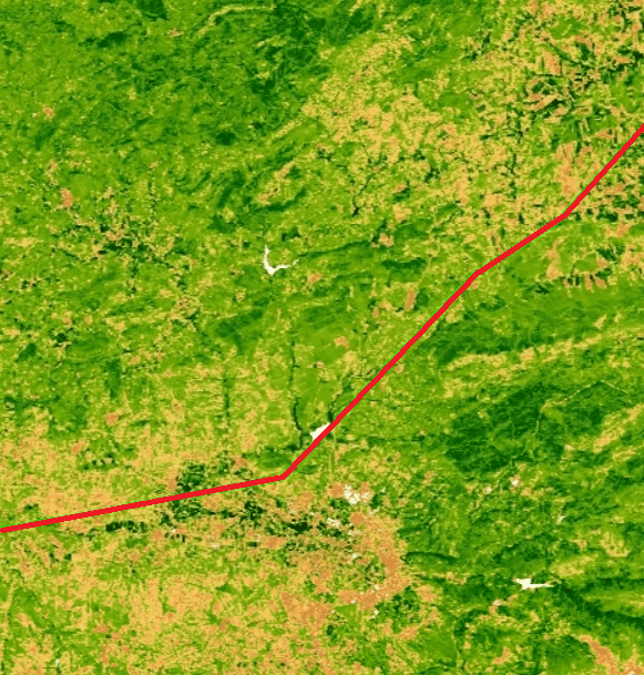
In both figures, we observe the electric cable line system. In the Cubillas map, a threshold is indicated: areas that can be excluded from inspection are marked in orange, while those that require checking are shown in black. On the Sierra Morena map, we see the average NDVI value for each pixel along with the red cable line system. The color gradient reflects the NDVI values—brownish areas indicate values closer to -1, representing sparse or no vegetation, while greener areas indicate values closer to +1, representing denser vegetation.
2. Residual Neural Network training to spot shadows and trees
After applying our NDVI filter, which discards a significant portion of the total area, we can identify the specific zones that need further inspection. At this stage, we must train our neural network to accurately identify both shadows and trees within these zones. This training will enable the system to distinguish critical features and enhance the precision of vegetation monitoring, ensuring that areas posing potential risks to the electric system are accurately detected and addressed.
As mentioned before, we decided to use images from Pleiades satellites, as they allow a low revisit time, and a very high image resolution, both really useful to periodically check how the vegetation is growing, and to help our network to identify the trees in an easier way.
The Pleiades satellites provide orthorectified images, which remove the error we can commit by not taking into account the satellite’s position. We also decided to use a Resnet, as it has demonstrated state-of-the-art performance in image segmentation tasks. ResNet’s ability to effectively handle complex image features and deep networks makes it ideal for accurately identifying and segmenting trees and shadows in our dataset, further improving the precision of our vegetation monitoring system.
The training process consists of a high number of images taken from Pleaides satellites in different zones, and their segmentation masks, ground truth for shadows and trees. This process is highly time-consuming, as it requires a large number of images along with their corresponding segmentation masks. Creating these masks is a manual and labor-intensive task, though some applications can assist in the mask-generation process. Despite these tools, the overall effort involved in preparing and labeling the data remains significant, adding complexity to the training of the neural network.
Once the network is trained, it can be used for inference. It will take an orthorectified image, preferably from Pleaides satellites for enhanced recognition accuracy, and output three class probability images, each corresponding to a specific attribute. These images will have the same dimensions as the input image and will represent the probability of each pixel belonging to one of three classes: the second image will indicate the probability of the pixel being a shadow, the third will represent the probability of it being a tree, and the fourth will represent the probability of it not being a tree or a shadow.
Each pixel is assigned a probability value between 0 and 1, indicating the model’s certainty of the pixel’s classification. In the output images, these values are visualized using a color spectrum from blue (0) to yellow (1), where blue indicates lower certainty and yellow represents higher certainty.
Following this, we will establish a threshold to produce a final image that classifies each pixel as either shadow, tree, or background. This classification allows for highly precise measurements of the distance between shadows and the centroid of the trees, enhancing the accuracy of vegetation monitoring near critical infrastructure.
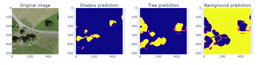
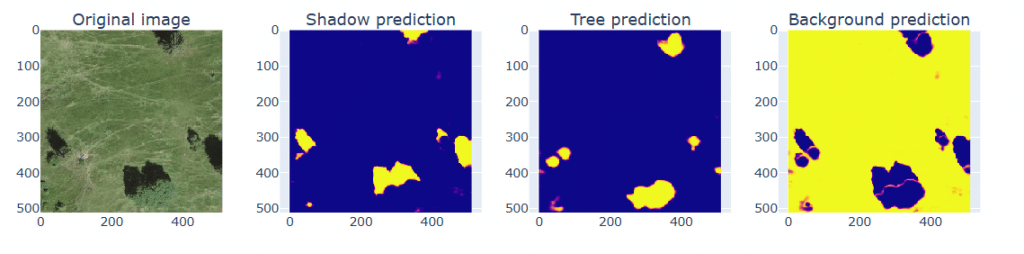
The first image in each row depicts the original image processed by the ResNet model, the second one shows the predicted presence of shadows, the third image highlights the presence of trees, and the fourth image indicates areas where neither a tree nor a shadow is present. These color-coded predictions allow for clear visualization of the model’s output and help in identifying the respective regions without the analyzed area.
3. Shadow direction calculator
While not strictly necessary, knowing the shadow’s direction vector can significantly enhance the precision of our estimations. Several applications, such as SunEarthTools, can calculate the Sun’s position at a specific location and time, or we can calculate it manually by determining the solar azimuth angle, which represents the Sun’s position relative to true north. The shadow will fall directly opposite to this angle.
The required equations are readily available, but in summary, we only need to determine the solar elevation angle (often found in the image metadata), the local hour angle, the solar declination angle (easily calculated), and the geographical zone where we want to compute the shadow’s direction coordinates. By incorporating this data, we can better estimate the precise shadow orientation, leading to more accurate monitoring and measurement.
4. Neural Network for Tree geo-positioning
We used YOLO, (You Only Look Once), a real-time object detection algorithm that processes an image to identify and locate objects quickly and accurately. We trained it the same way we trained the ResNet model mentioned in point 2 but, instead of using segmentation masks, we needed to create a list of bounding boxes for each tree.
It is useful in our case because it provides an instance for each tree, allowing us to calculate the height of each tree one by one and helping to identify them in case a multitude of trees is too close to each other.
This is also a very time-consuming process but we can speed it up by just calculating the boundaries of the trees’ segmentation masks created in the previous neural network.
After training our YOLO model, we’ll have a list with the centroid of each tree. With the purpose of calculating each individual tree height, an assumption is made: the center of the box is the center of the tree, which might not be accurate in all cases. This is, therefore, an aspect for further improvement beyond this MVP (Minimum Viable Product) as different methods can be applied to palliate the potential error, such as calculating the distance not to the centroid, but to the line that intersects with the centroid and is perpendicular to the shadow’s direction.
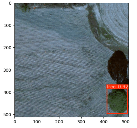
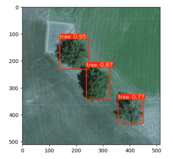
For both images, we can see the YOLO predictions. Each red box indicates the presence of a tree followed by the certainty of its prediction (value from 0 to 1, as a probability).
5. Height calculation and threshold estimation
In this step, we gather the information processed by the previous modules to first calculate the shadow’s direction vector, which is consistent for all trees in the image. Next, we determine the furthest point identified as a shadow by our ResNet model that corresponds to the tree we are analyzing.
This is achieved by leveraging the bounding box data from the YOLO model. We begin by calculating the box that defines the tree’s diagonal line. For each point along this diagonal, we draw a line following the shadow’s direction. We extend the line until it intersects a point that is classified as something other than a shadow, marking this position. This process helps pinpoint the furthest point of the tree’s shadow, contributing to more precise measurements of its extent and potential impact on nearby infrastructure.
After completing this process, we will have a list of coordinates representing the furthest points of the tree’s shadow. From this list, we simply select the coordinate that maximizes the distance from the tree’s centroid. Depending on the geographical area and the type of trees common to the region, we can adjust this method to use different distance metrics, optimizing accuracy for specific environmental conditions. This step ensures that we account for the maximum potential reach of the tree’s shadow, enhancing the precision of our vegetation risk assessment.
Finally, with the shadow length determined, we can convert it into meters using the information from the image metadata to calculate the real height of the tree. This can be done using the formula:
H = L’ * tan(O), where H represents the tree’s height, L’ is the shadow’s length, and O is the Sun’s elevation angle.
Since we are monitoring cable systems, it’s essential to consider that the cables form a catenary curve. This curve causes the cables to sag between support towers, with the lowest point typically located near the center of the span. To ensure safe clearance between the cables and surrounding vegetation, we can calculate the height at the cable’s lowest point and compare it to the heights of nearby trees. For example, we can establish a threshold—such as checking whether any tree height exceeds 70% of the cable’s lowest height.
Monitoring tree heights is crucial for the effective management of electric cable systems. By accurately measuring tree heights, utilities can ensure that vegetation remains within safe clearance zones around power lines, helping to prevent potential power outages and safety hazards caused by contact with the infrastructure.
Conclusion
The promising results from the initial testing of our TreeSight application validate the effectiveness of our approach. We are making steady progress toward completing the productization of the application in the near future. We have identified several aspects across different areas to further develop our application, including:
- Time interval NDVI filter: Implementing the NDVI filter across different dates allows us to monitor vegetation changes over time and interpolate its growth rate. By tracking these variations, we can better predict how quickly vegetation is approaching critical infrastructure, enabling more proactive management and timely interventions.
- More data: Data availability remains a challenge, but increasing the number of images—both through data augmentation and the collection of real data—would significantly enhance the accuracy of our model predictions. Expanding the dataset would enable the neural networks to learn more effectively, resulting in more precise and reliable outputs.
- Terrain elevation: Integrating topographic data that provides precise terrain elevation information when measuring shadows can significantly reduce errors, especially in uneven or hilly terrain. This additional data helps account for elevation changes, leading to more accurate height calculations and improving overall precision in vegetation monitoring.
- Different models/approach: As detailed above, we first conduct semantic segmentation to assign each pixel to a given class. For the shadow calculation of each tree, we need to know the location of each tree in the image- hence the object detection using YOLO. We chose this approach because we already had the training pipeline and the model for the semantic segmentation available. Another approach to achieve a similar result could be setting up a panoptic segmentation using, for example, Detectron2.
TreeSight demonstrates the significant potential of applying advanced technologies to address complex challenges related to critical infrastructure, leveraging Earth Observation data and cutting-edge algorithms. Its ability to analyze vast datasets with precision not only enhances operational efficiency but also improves safety and reliability in infrastructure management. This highlights the transformative role that technology can play in solving intricate, large-scale problems in critical sectors.
About Cactus
Cactai team, a space geek team, is ready to further explore your use case and tailor a solution based on EO to meet your specific needs. Whether you’re looking to optimize processes, integrate advanced technologies, or innovate within your industry, we’re here to collaborate with you every step of the way. Our goal is to ensure that your objectives are met with precision and excellence, providing the expertise and support needed to achieve success.